| [Trailable switch machine] | |
Title of invention (designation in Request for Grant suffices)
 |
|
The present invention relates to a trailable switch machine with a thrust rod which shifts the switch-point tongues, and also with a coupling device which is disposed between a driving unit and the thrust rod and has a retaining roller which, in the coupled condition, engages in a spring-loaded manner in a recess in the thrust rod.
|
R. 27(1)(a)
Technical field to which invention relates
|
|
Arrangements of the above type are known for example from DE-B2 xx xx xxx, DE-B1 xx xx xxx or DE-B2 xx xx xxx and allow trailing of the switch as required for many switch machine applications, even with generally required locking of the switch drive in the end positions of the switch-point tongues. For that reason the coupling device is slidably mounted on the thrust rod and contains a retaining roller which is pressed by a retaining spring into a trough-shaped depression in the thrust rod. Thus spring force and the shaping of the depression and the retaining roller defines a threshold force beyond which the otherwise practically rigid connection of the thrust rod to the coupling device and hence to the drive unit is released. This form of automatic coupling functions very reliably, and its only significant disadvantage is the relatively large amount of space it takes up, which limits its usability for various applications and has unwanted consequences in terms of restricting flexibility in the disposition of other components of the switch machine.
|
R. 27(1)(b)
Relevant prior art with citations
|
|
The object of the present invention is to improve a switch machine of the above type such that the said disadvantages of the known arrangements are avoided and that in particular the coupling device can be disposed in a simple and space-saving fashion between the drive unit and the thrust rod, with reliable operation also guaranteed.
|
R. 27(1)(c)
Technical problem to be solved
|
|
The invention achieves this object for a switch machine of the above type by providing two counter-rollers which are disposed substantially symmetrically with respect to the direction of movement of the retaining roller and are mounted so as to be displaceable essentially perpendicularly to the direction of movement of the said retaining roller and which are loaded by at least one retaining spring in the direction of abutment against the retaining roller. In that way it is possible in a very simple fashion to circumvent the previously existing need to dispose the retaining spring loading the retaining roller in the direction of movement of the retaining roller, ie normally standing out perpendicularly from the thrust rod. There is great flexibility as regards the disposition of this retaining spring, as it now acts on the retaining roller only indirectly via the counter-rollers, allowing for a very compact design for the coupling device while keeping essentially the same function.
|
R. 27(1)(c)
Disclosure of invention
|
|
In further embodiments of the invention, the retaining spring - as hitherto in most cases - is constructed as a helical compression spring, but it may now be disposed essentially parallel to the thrust rod, which is optimal with regard to the above-mentioned space-saving design.
|
R. 27(1)(c)
Advantageous effects of invention
|
According to an especially preferred further development of the invention, the retaining roller is mounted, at least on one side, in a sliding block which is guided, perpendicularly to the thrust rod, in a housing belonging to the coupling device, and the two counter-rollers are disposed on counter-roller housings which are displaceable, parallel with the thrust rod, in the housing of the coupling device and are loaded against one another via the retaining spring. This produces a very simple and reliably functioning construction, as the spring force acting on the counter-rollers is directly transmitted to the loading of the retaining roller.
Although two or even more retaining springs may of course also be provided if necessary to load the counter-rollers relative to the retaining roller, a further embodiment of the invention that has proved particularly advantageous is one in which a single retaining spring acts, on the one hand, directly on one of the counter-roller housings and, on the other hand, on the other counter-roller housing via a tensioning piece with an adjusting screw and via transmission bars. Although the design is very simple, it also provides for adjustability of the desired threshold force for releasing the rigid coupling between the thrust rod and the drive unit.
|
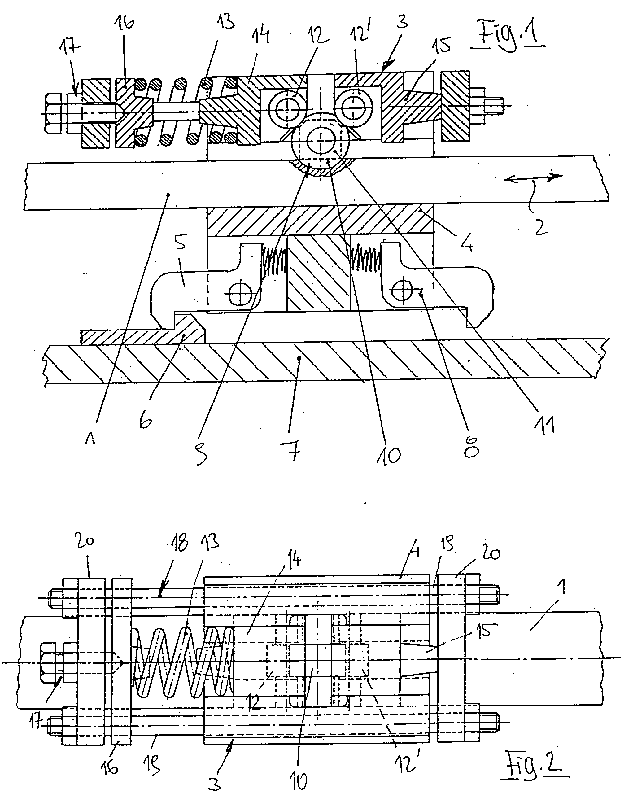
The invention will now be elucidated by reference to the embodiment partially illustrated schematically in the drawings. Fig. 1 shows a partial cross-section through a switch machine according to the invention in the area of the coupling device between the drive unit (not shown) and the thrust rod, while Fig. 2 shows a partial plan view of the arrangement according to Fig. 1 from above.
|
R. 27(1)(d) and (e)
Description of at least one way of carrying out invention with reference to drawing(s)
|
A thrust rod 1 which, when required, displaces the switch-point tongues (not shown) is movable in the direction of double-headed arrow 2, the actual drive unit (not shown) acting on the thrust rod 1 via a coupling device 3. In the left-hand end position of the thrust rod 1 shown in Fig. 1, a left-hand locking bar 5 held by spring force against the housing 4 of the coupling device 3 is engaged in a catch 6 on the housing base 7, thereby fixing the associated end position of the switch-point tongues actuated by the thrust rod 1. Numeral 8 is a right-hand locking bar which in turn is held by spring force against the housing 4 and in the right-hand end position of the thrust rod 1 engages in an equivalent catch (not shown) on the housing base 7.
Of no further interest here are the mechanisms which, when drive unit actuation begins, result first in release of the locking bar 5 or 8 and only then in a corresponding displacement of the coupling device 3 or the thrust rod 1.
To enable trailing of the switch actuated by the thrust rod 1 even in the end positions locked by the appropriate locking bars 5 and 8 without damaging the switch machine, the coupling device 3 has a retaining roller 10 which, in the illustrated coupled condition, engages in a spring-loaded manner in a recess 9 in the thrust rod 1 and here is mounted on either side in a sliding block 11 which is guided, perpendicularly to the thrust rod 1, in the housing 4 of the coupling device 3. Also, two counter-rollers 12, 12' are provided which are disposed substantially symmetrically with respect to the direction of movement of the retaining roller 10 imparted by the sliding blocks and are mounted so as to be displaceable essentially perpendicularly to the direction of movement of the retaining roller 10 and which are loaded by a retaining spring 13 in the direction of abutment against the retaining roller 10.
The retaining spring 13 is here constructed as a helical compression spring and is disposed essentially parallel with the thrust rod 1, producing a very compact construction while ensuring reliable operation of the coupling device 3.
The two counter-rollers 12, 12' are disposed on counter-roller housings 14, 15 which are displaceable, parallel with the thrust rod, in the housing 4 of the coupling device 3 and are loaded against one another via the retaining spring 13. For this purpose the single retaining spring 13 here acts at one end directly on the counter-roller housing 14 and at the other end on the other counter-roller housing 15 via a tensioning piece 16 with an adjusting screw 17 and via transmission bars 18 - here essentially formed by the two threaded rods 19 and the caps 20 - which enables the effect of the spring force to be diverted in a very simple manner to the loading of the retaining roller 10.
When the switch is trailed, the thrust rod 1 (with the coupling device and retaining roller 10 locked by locking bar 5 or 8) with its recess 9 moves out of the engagement area of the retaining roller 10, pushing the retaining roller 10 back against the effect of the spring-loaded counter-rollers 12, 12', which in turn are pushed apart along with the counter-roller housings 14, 15. The thrust rod 1 is thus freely displaceable relative to the coupling device 3 and the drive unit until coupling takes place again when the position of the retaining roller 10 aligns with the recess 9.
Instead of the illustrated single retaining spring 13 constructed as a helical spring, it would of course also be possible to use two or more springs, also constructed for example as disk springs or similar, possibly also disposed on both sides of the retaining roller 10; another possibility would be an arrangement, differing in terms of angle from that illustrated, of the degrees of movement of the retaining roller 10 and/or of the counter-rollers 12, 12', enabling allowance to be made where necessary for specific local conditions.
|
5.
|
Trailable switch machine with a thrust rod which shifts the switch-point tongues, and also with a coupling device which is disposed between a driving unit and the thrust rod and has a retaining roller which, in the coupled condition, engages in a spring-loaded manner in a recess in the thrust rod,
|
|
characterised in that two counter-rollers (12, 12') are provided which are disposed substantially symmetrically with respect to the direction of movement of the retaining roller (10) and are mounted so as to be displaceable essentially perpendicularly to the direction of movement of the said retaining roller (10) and which are loaded by at least one retaining spring (13) in the direction of abutment against the retaining roller (10).
|
R. 29(1)(b)
Characterising portion
|
|
6.
|
Switch machine according to claim 1,
|
|
R. 29(3), (4)
Dependent claim
|
characterised in that the retaining spring (13) is constructed as a helical compression spring and is disposed essentially parallel with the thrust rod (1).
|
7.
|
Switch machine according to claim 1 or 2,
|
|
characterised in that the retaining roller (10) is mounted, on at least one side, in a sliding block (11) which is guided, perpendicularly to the thrust rod (1), in a housing (4) belonging to the coupling device (3), and that the two counter-rollers (12, 12') are disposed on counter-roller housings (14, 15) which are displaceable, parallel with the thrust rod (1), in the housing (4) of the coupling device (3) and are loaded against one another via the retaining spring (13).
|
|
8.
|
Switch machine according to claim 3,
|
|
characterised in that a single retaining spring (13) acts, on the one hand, directly on one of the counter-roller housings (14) and, on the other hand, on the other counter-roller housing (15) via a tensioning piece (16) with an adjusting screw (17) and via transmission bars (18).
|
|
In a trailable switch machine a coupling device (3) is arranged between a drive unit and the thrust rod (1) and has a retaining roller (10) which is spring-loaded in the coupled-end state and engages in a depression (9) of the thrust rod (1). In order to be able to realise such a coupling device even when the space available is very restricted, two counter-rollers (12, 12') are provided which are arranged essentially symmetrically with respect to the direction of movement of the retaining roller (10) and are mounted so as to be capable of moving essentially perpendicularly with respect to the direction of movement of the retaining roller (10) and are loaded by at least one retaining spring (13) in the direction of abutment against the retaining roller (10).
|
R. 33(2), (3), (5)
Content of abstract
|
|

 ANNEX III Examples of European patent applications
 2. Electricity/physics example